Article: The Invisible Fault: How Cable Failures Actually Happen in Professional Audio

The Invisible Fault: How Cable Failures Actually Happen in Professional Audio
6 min read · Category: Live Sound, Installation, Studio
In professional audio troubleshooting, cables are statistically the most probable point of failure in any signal chain. ProSoundWeb, one of the sector's most authoritative technical publications, puts it plainly: when a fault appears in a vocal microphone chain, the cable is more likely to be the cause than the microphone, the DI box, the stage box, or the console combined. The same logic extends through every segment of a professional audio system.
Yet cable failures are routinely underestimated at the specification stage, overcomplicating diagnosis in the field, and generating a disproportionate share of the callbacks, troubleshooting visits, and client conversations that define a technician's actual workload. The reason is not that people do not know cables can fail. It is that the failure modes that matter most are the ones that are hardest to see.
The five failure modes that professionals encounter most and manufacturers rarely discuss
Industry data from AVIXA and multiple AV integration firms identifies a consistent pattern: approximately 70% of intermittent signal problems in professional audio and AV environments trace to cables and connectors. Not amplifiers. Not software. Not network infrastructure. Cables and connectors.
What that figure conceals is more important than what it reveals. The failure modes within that 70% are not random — they cluster around five specific mechanisms, each with its own timeline, its own symptom presentation, and its own root cause that sits far upstream of the moment the fault appears.
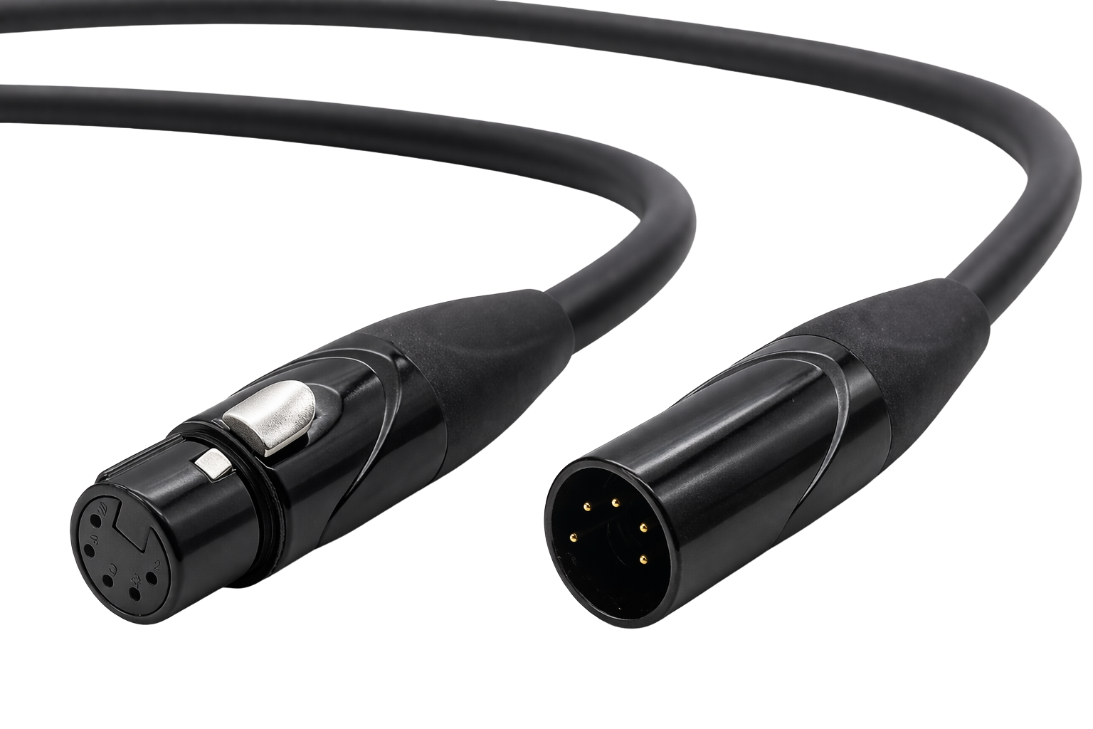
1. Connector oxidation: the fault that builds for months
Oxidation at the contact surface of a connector does not announce itself. It accumulates. In a permanent installation environment, a connector terminating inside a wall, under a floor, or behind a rack is exposed to atmospheric oxygen and daily thermal cycling — the building warming and cooling with the occupancy cycle — over months and years. At standard copper contact surfaces, oxidation increases electrical resistance at the contact interface progressively and invisibly.
The fault presentation is characteristically intermittent and temperature-dependent. The system works. Then it does not. Then it works again. Reproducing the fault on a bench is often impossible, because the fault only manifests under the specific thermal and atmospheric conditions of the installed environment. The technician replacing the cable months later is not fixing a broken cable — they are rectifying a material specification decision made at the original install.
The oxidation resistance of a conductor matters here beyond the conductor itself. An OFC conductor at 99.99% purity introduces fewer impurity sites at the termination interface than standard copper, which reduces the rate at which oxidation develops at the most critical electrical junction in the cable — the point where conductor meets connector body.

2. The micro-crimp gap: the fault that cannot be found on a bench
A connector crimped slightly off-specification — too little force, slightly misaligned tooling, an imperceptible variation in wire seating depth — produces a contact gap that is physically invisible and electrically negligible under ambient conditions. The resistance across the junction measures within acceptable parameters on a cable tester. The cable passes QC.
Under thermal expansion, mechanical vibration, or the cable flex of a live show, the gap opens fractionally. Contact resistance jumps. Signal integrity drops. The fault presents as an intermittent dropout or a noise floor spike that cannot be reproduced in the controlled environment where the diagnosis happens.
This is the failure mode that generates the most expensive callbacks in professional installation. It is also the failure mode most directly linked to connector quality and termination process — specifically, the mechanical precision of the connector's contact geometry and the consistency of the termination tooling. A connector engineered for dimensional consistency across thousands of terminations produces fewer micro-crimp gaps than a connector manufactured to a cost target. The difference is not visible in the product. It is visible in the fault rate 14 months later.
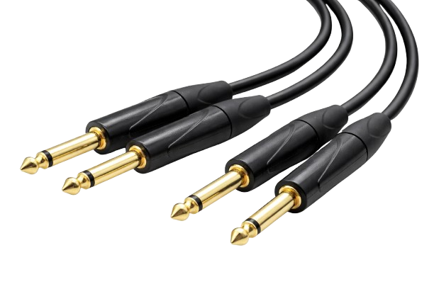
3. Conductor fatigue: the touring cable problem that takes 200 shows to manifest
Touring cables are subject to a failure mode that permanent installation cables are not: repeated mechanical cycling. A cable packed and unpacked 200 times in a touring season is flexed, coiled, uncoiled, stepped on, pulled through cable runs, and subjected to repeated bend-cycle loading at every point along its length — but most severely at the connector entry point, where the cable transitions from the constrained geometry of the connector boot to free movement.
Standard copper conductors are more brittle under repeated flex than OFC. At the microscopic level, standard copper's higher impurity content creates grain boundary weaknesses that propagate under cyclic mechanical stress. OFC's higher purity produces a more uniform crystalline structure with better fatigue resistance. The practical difference: a standard copper cable in a touring rig may begin to show conductor fatigue fractures — presenting as crackling under cable movement, clean at rest — after 200 to 400 pack/unpack cycles. An OFC cable of equivalent construction will typically last significantly longer under the same conditions.
This failure mode is particularly insidious because it is position-dependent: the cable may test clean in isolation but fail in use because the fault only manifests under the mechanical loading of a specific cable run angle. Engineers who have traced these faults know the pattern: move the cable, hear the crackle. Test it on the bench, it is fine.
4. Insulation breakdown: the long-term installation failure
In permanent installations, insulation quality determines how the cable behaves at year three and year five, not year one. Low-grade insulation compounds develop micro-cracking under thermal cycling — the same daily heat/cool cycle that drives connector oxidation. At tight bend points inside conduit elbows, around rack edges, or where cables are bunched under load, thermal fatigue accelerates.
The failure presentation is a rising noise floor — often attributed initially to an external RF source — or increased susceptibility to interference in environments with dense radio frequency activity. Replacing the cable resolves it. The post-mortem diagnosis, if anyone performs one, finds micro-cracks in the insulation jacket concentrated at the bend points, with consequent increase in capacitance and degraded shielding effectiveness.
Installation-rated cable construction specifies insulation compounds for static routing: compounds that resist thermal cycling, maintain flexibility without cracking, and maintain specified capacitance values over the installation lifetime. This is a different specification requirement from touring cable, where flexibility under repeated coiling is the primary demand. Using touring-spec cable in a permanent installation, or permanent-install cable on a touring rig, is a material mismatch that will express itself eventually.
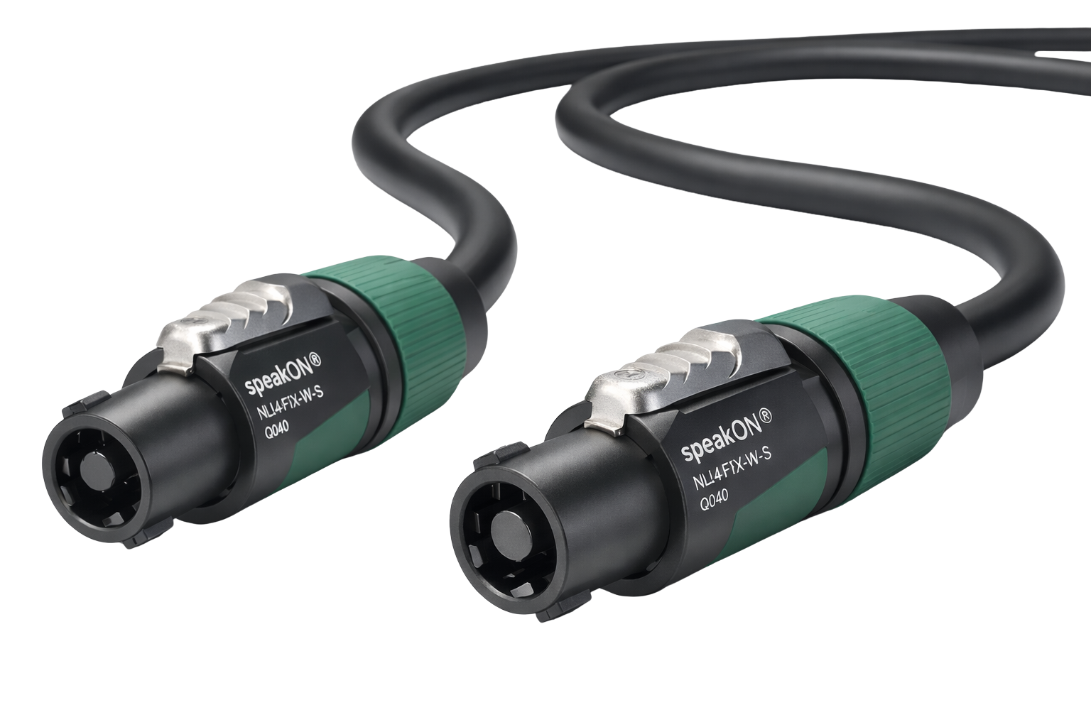
5. Strain relief failure: the fault that everyone overlooks
The strain relief — the mechanical component at the connector entry point that distributes cable pull force away from the electrical connection — is the least discussed component in professional audio cabling and one of the most consequential failure modes in daily use.
A strain relief that transfers mechanical load correctly ensures that when a cable is pulled, bent, or stepped on, the force is absorbed by the boot and housing, not transmitted to the solder joint or crimp point. A strain relief that fails — either through poor design or through the common field practice of over-tightening or under-tightening — transfers that force directly to the conductor-to-contact junction. The failure is slow. After weeks or months of daily use, the conductor begins to fatigue at that single point. The fault presents as intermittent signal at the connector exit. Move the cable near the connector and the dropout appears or disappears.
Jonah Altrove, writing in ProSoundWeb, notes the underlying cause that accelerates this failure in field use: tying off a wrapped cable using the cable itself rather than a tie line. This single practice — universal in under-resourced setups — puts constant tensile stress on exactly the point where the cable is already most mechanically vulnerable. The connector entry. The most common failure point.
 The pattern behind the pattern
What connects these five failure modes is not bad luck. It is not component age. It is the same root cause expressed in five different ways: a specification decision made before installation, before the tour, before the show, that did not account for the real conditions the cable would face.
The conductor purity determines oxidation rate. The connector quality determines crimp consistency. The cable construction determines fatigue resistance. The insulation specification determines long-term dielectric stability. The strain relief design determines mechanical load transfer. Every one of these variables is fixed at the moment of specification. None of them can be improved retroactively once the cable is in the wall or in the touring trunk.
In professional audio, the cable is almost always the most likely failure point. But the specification decision that determines whether it fails was made months or years before the fault appears.
This is the gap between how cable failure is discussed in the industry and how it actually works. The industry talks about failure as something that happens during use. The reality is that failure is determined at specification.
What this looks like in practice: three scenarios
The permanent installation
A conference centre AV installation: 12 meeting rooms, full audio distribution, approximately 650 cable terminations, signed off and operating cleanly. At the 11-month mark, one room begins intermittent dropout — reproducible under certain room temperatures, absent at others. The fault traces to connector oxidation at a single XLR termination inside a wall void. The cable used was not rated for static installation. The connector was a low-cost generic. The termination was done correctly at install. None of that was visible until month eleven.
The rectification: open the wall, replace the cable run, re-terminate. Two days of labour on a job that was completed and invoiced eight months earlier.
The touring rig
A touring instrument cable — 6-metre, used across a 40-date run — begins presenting crackling at the guitar signal during the second half of shows, clean at soundcheck. The fault is position-dependent: specific to the angle the cable sits in at the pedalboard connection point. Cable tester shows continuity. The fault is conductor fatigue at the connector entry, where 200-plus coiling cycles have concentrated flex stress at the point the strain relief failed to adequately distribute.
The rectification: cable replacement mid-tour. Cost: cable plus the 20 minutes of soundcheck time spent tracing a fault that presented as a guitar problem, then an amp problem, before the cable was finally substituted.
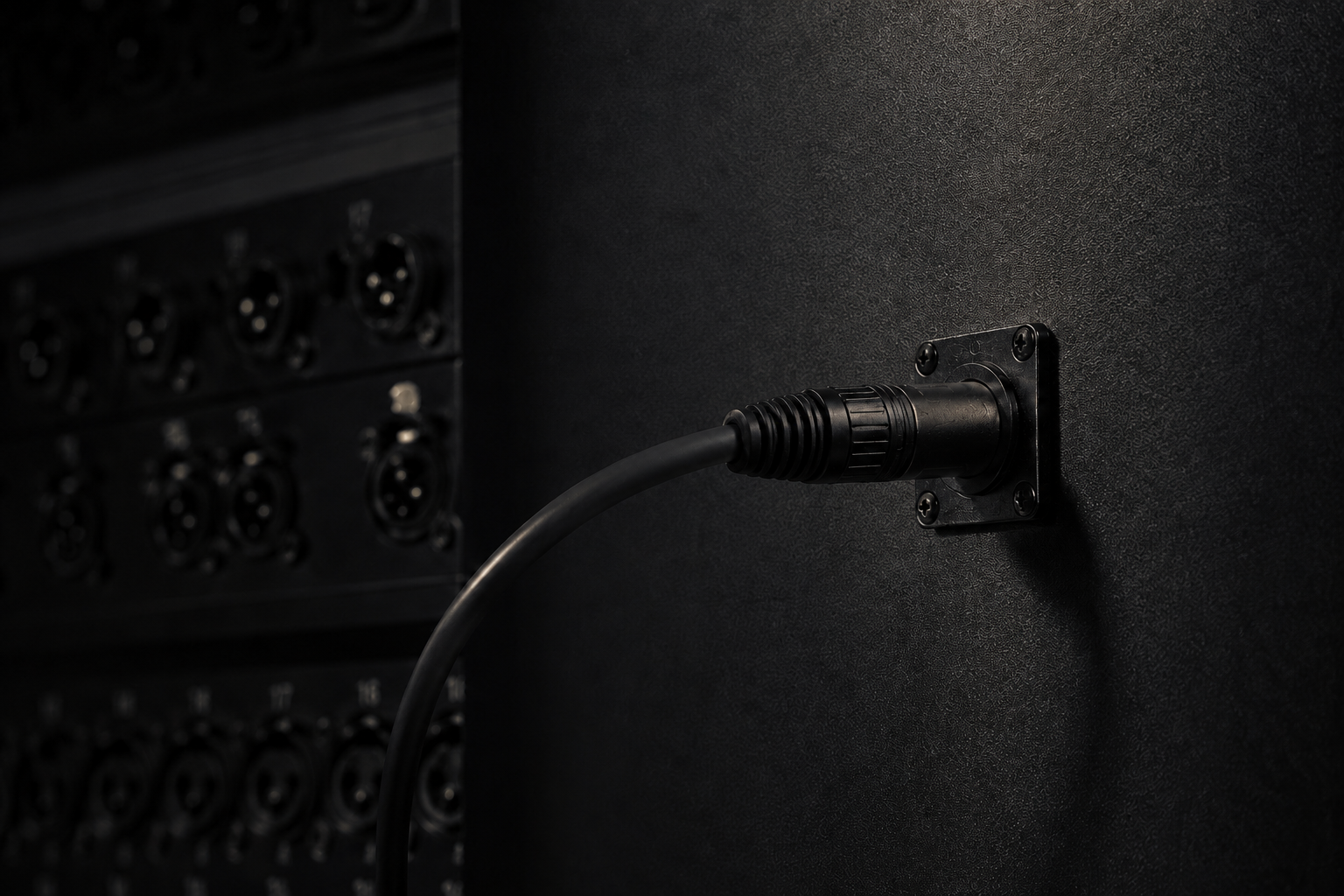
The live sound show fault
A vocal microphone chain goes intermittent during a monitor engineer's pre-show check — a noise on the first wireless frequency. Systematic elimination: check patches, check DI switches, check power. The fault is in a cable connecting the stagebox to the console — a cable that has passed every show prior to this one, that tests clean on the bench after the show, and that fails again two weeks later under similar temperature conditions. The mechanism: micro-crimp gap at the XLR termination, opening fractionally under the specific thermal conditions of the performance space.
This is the cable that should have been replaced at the first hint of intermittent behaviour. It was not, because it always tested clean. That is the nature of the micro-crimp gap: it hides from the bench.
The failure mode matrix
The table below maps the five primary cable failure modes in professional audio to their field presentation, typical timeline, root cause, and prevention approach. It is intended as a reference for specification decisions, not a troubleshooting guide — because the point of the matrix is that prevention is the only reliable response to most of these failure modes. By the time the fault presents, the specification decision that caused it cannot be undone.
|
Failure Mode |
How it presents |
When it appears |
Root cause |
Prevention |
|
Connector oxidation |
Intermittent dropout, noise floor rise |
Month 8–18 post-install |
Poor contact plating + thermal cycling |
Spec quality connectors; OFC conductor |
|
Micro-crimp gap |
Dropout reproducible only under temperature / vibration |
Variable — sometimes never on bench |
Off-spec termination pressure |
Consistent tooling; post-termination test |
|
Conductor fatigue |
Crackling under cable movement, clean at rest |
200–400 pack/unpack cycles in touring |
Standard copper brittle under repeated flex |
OFC conductors; correct bend radius |
|
Insulation breakdown |
Rising noise floor, RFI pickup in dense RF environments |
Year 2–3 in permanent install |
Low-grade insulation compounds crack under thermal stress |
Installation-rated jacket specification |
|
Strain relief failure |
Intermittent signal at connector exit point |
Weeks–months of daily use |
Force transferred to conductor instead of relief body |
Mechanical connector spec; cable support |
The specification implications
Each failure mode in the matrix has a corresponding specification response that addresses it before installation, not after. None of them are exotic or expensive in absolute terms — they are the difference between specifying for day-one performance and specifying for year-three reliability.
– Connector oxidation: OFC conductor at verified purity; quality-specified connector plating for the application environment (touring vs static install)
– Micro-crimp gap: connector mechanical specification for dimensional consistency; post-termination testing under load, not just continuity check
– Conductor fatigue: OFC conductor in touring cable; correct bend radius maintained at strain relief; strain relief designed and installed for the mechanical load of the specific application
– Insulation breakdown: installation-rated insulation compound for static routing; touring-rated compound for repeated flex applications — these are not interchangeable
– Strain relief failure: mechanical connector specification reviewed for application load; field practices (tie-off method, cable support) documented and followed
None of these requirements are new. They are understood by experienced engineers and veteran installers. What changes is who controls the specification decision — and whether that decision is made by someone who will be responsible for the fault when it appears at month fourteen, or by whoever found the cheapest cable option in the budget window.
The cost asymmetry
The cost of specifying correctly is a known quantity at time of purchase: the price difference between a quality-specified cable and a budget alternative, multiplied by the number of cable runs in the project. It is visible in the budget. It is easy to cut.
The cost of a callback is not visible at purchase. It is the technician's time to diagnose an intermittent fault that only presents in specific conditions. It is the cost of opening a wall or a cable run that was completed and invoiced. It is the cost of the client conversation that happens in front of a room that should be working. It is, in some cases, the cost of the relationship.
XTEN-AV, a professional AV integration research firm, documents the asymmetry: organisations with structured cable specification and maintenance plans experience 60% fewer emergency repairs than those without. The 60% figure is not the cost of the better cable. It is the cost of the callbacks that didn't happen.
In permanent installation, the math of the cable decision is not the purchase price of the cable. It is the purchase price of the cable minus the probability-weighted cost of the fault it will or will not generate over its installation lifetime. Most procurement decisions in professional AV do not calculate it that way. The ones that do tend not to need callbacks.
The cost of specifying correctly is visible at purchase. The cost of specifying wrong is visible at month eleven.
Installation / AV range — specified for permanent environments → ashercables.com/collections/installation-av
Reference series — OFC conductors, Neutrik connectors → ashercables.com/collections/reference
The ASHER Promise — our specification consistency policy → ashercables.com/pages/the-asher-promise
→ Previous: The Connector Is the Weakest Point — why we chose Neutrik → ashercables.com/blogs/signal/the-connector-is-the-weakest-point
→ Next article (planned): OFC Explained — what 99.99% purity actually means in the field
RESEARCH NOTE — FOR INTERNAL USE
SOURCES AND FIELD DATA
This article draws on the following verified professional sources:
– ProSoundWeb — Roundtable: A Treasure Trove of Advice About Cable & Interconnect (multi-engineer field experience including Jonah Altrove, Craig Leerman, Karrie Keyes, Andy Coules)
– ProSoundWeb — In The Moment: Getting Better At Troubleshooting Live Sound Problems (statistical prioritisation of cable as primary failure mode in signal chains)
– AVIXA Xchange — Troubleshooting Common AV Issues (70% of intermittent signal problems attributed to cables/connectors: Tekmax Technologies data)
– XTEN-AV — 7 Common AV Installation Problems and Their Solutions (45% of signal interference issues from poor wiring/cable management: 21st Century AV data; 60% fewer emergency repairs with structured maintenance: XTEN-AV research; 78% lower connectivity failures with professional-grade cables: ATXES research)
– FOH Magazine — Audio Fails and Other Sonic Disasters (field accounts from FOH engineers on cable and connector failure modes in live production)
Leave a comment
This site is protected by hCaptcha and the hCaptcha Privacy Policy and Terms of Service apply.